Device Profile
Overview
Device Profiles define the essential radio parameters and capabilities of LoRaWAN devices used by OmniWOT’s IoT infrastructure. They form the communication blueprint, ensuring smooth onboarding, configuration, and device behavior for uplink/downlink communication within the LoRaWAN network via ChirpStack.
Types of Device Profiles
1. System Profiles
Definition: Predefined templates provided by OmniWOT.
Purpose: Streamlines setup by using vendor-verified configurations.
Use Case: Ideal for widely used or standard devices from manufacturers like Milesight, Dragino.
Editing: System profiles are read-only to ensure reliability and consistency.
Example Devices:
- WS503_CN Smart Wall Switch
- EM300-MCS Magnetic Contact Switch
2. Custom Profiles
- Definition: User-created profiles tailored for specific deployments or unique device behavior.
- Purpose: Offers flexibility to define non-standard configurations, custom payloads, codecs, and measurement logic.
- Use Case: Required when working with prototype devices or unique configurations.
- Editing: Fully editable by the user.
Device Profile Components
Each Device Profile comprises the following configuration sections:
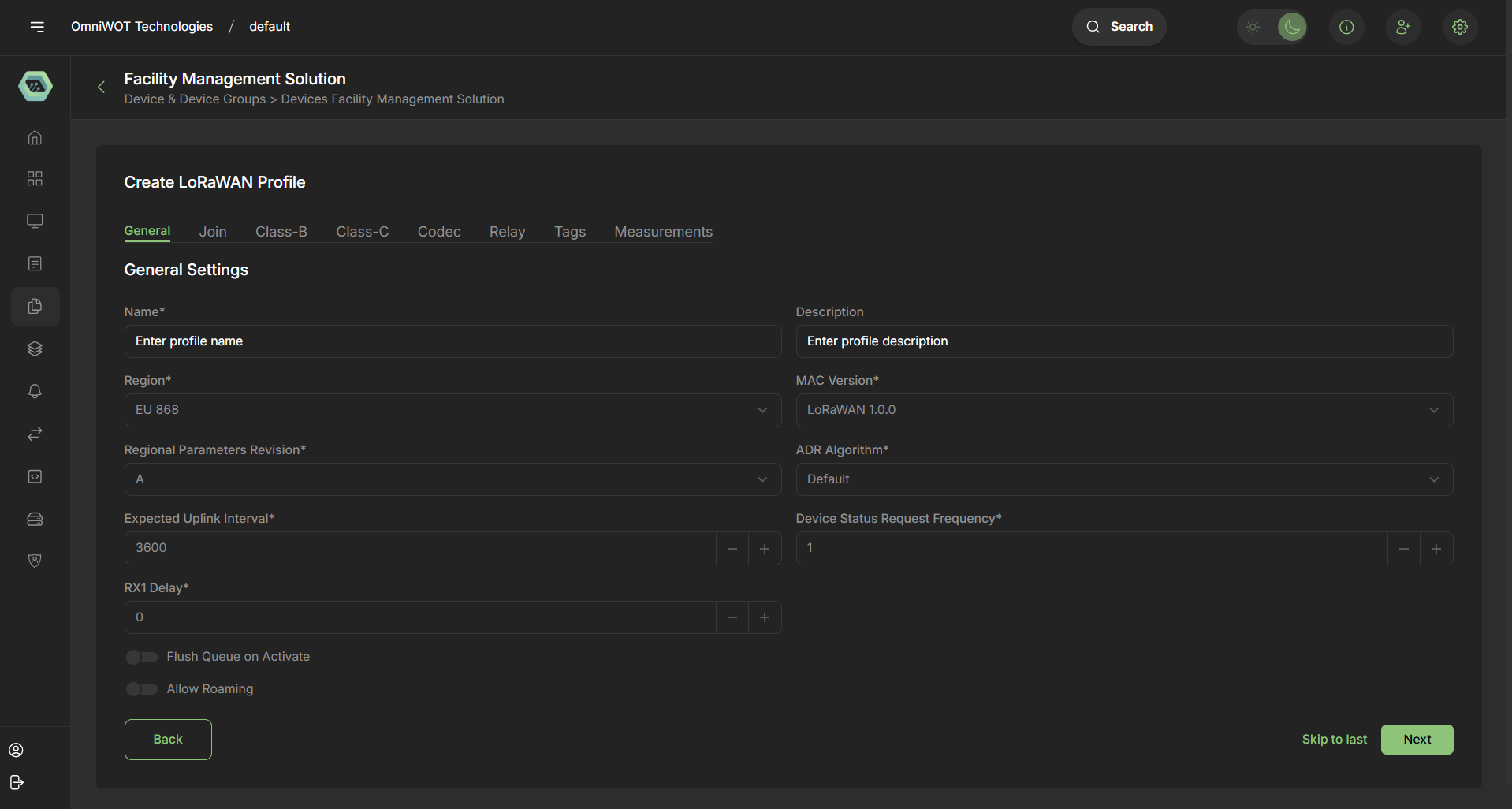
1. General Settings
- Name
- Description
- Region (e.g., EU868)
- MAC Version (e.g., LoRaWAN 1.0.0)
- Regional Parameters Revision (e.g., A)
- ADR Algorithm (e.g., Default)
- Expected Uplink Interval (in seconds)
- Device Status Request Frequency (in uplinks)
- RX1 Delay
- Flags: Flush Queue on Activate, Allow Roaming
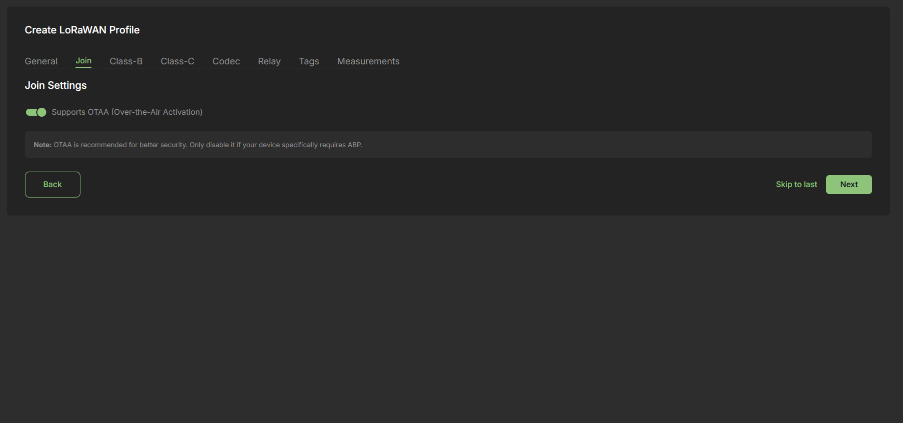
2. Join Settings
Supports OTAA (Over-The-Air Activation)
- Recommended for enhanced security.
Fallback to ABP (Activation By Personalization) where necessary.
3. Class B Settings
- Class B Support Toggle
- Beacon-based synchronization required
- Scheduled downlink slot configuration
4. Class C Settings
- Class C Support Toggle
- Continuous receive mode when not transmitting
- High power consumption - best for mains-powered devices
5. Codec Configuration
Payload Codec Type:
- None
- Cayenne LPP
- JavaScript (Custom Functions)
Purpose:
Convert binary payloads to JSON for easier interpretation.
Example JS decoder:
function decodeUplink(input) {
  return {
    data: {
      temp: 22.5,
    },
  };
}
6. Relay Configuration
Relay Modes:
- Is Relay Device (acts as a repeater)
- Is Relay End-Device (can use relays to transmit data)
- Only Accept Data Through Relay (Optional)
Configuration:
- Channel configuration (e.g., bucket size, refresh rate)
- Uplink and Join Request limits
7. Tags
Custom Metadata:
- Vendor name
- Device model
- Application tag for device grouping
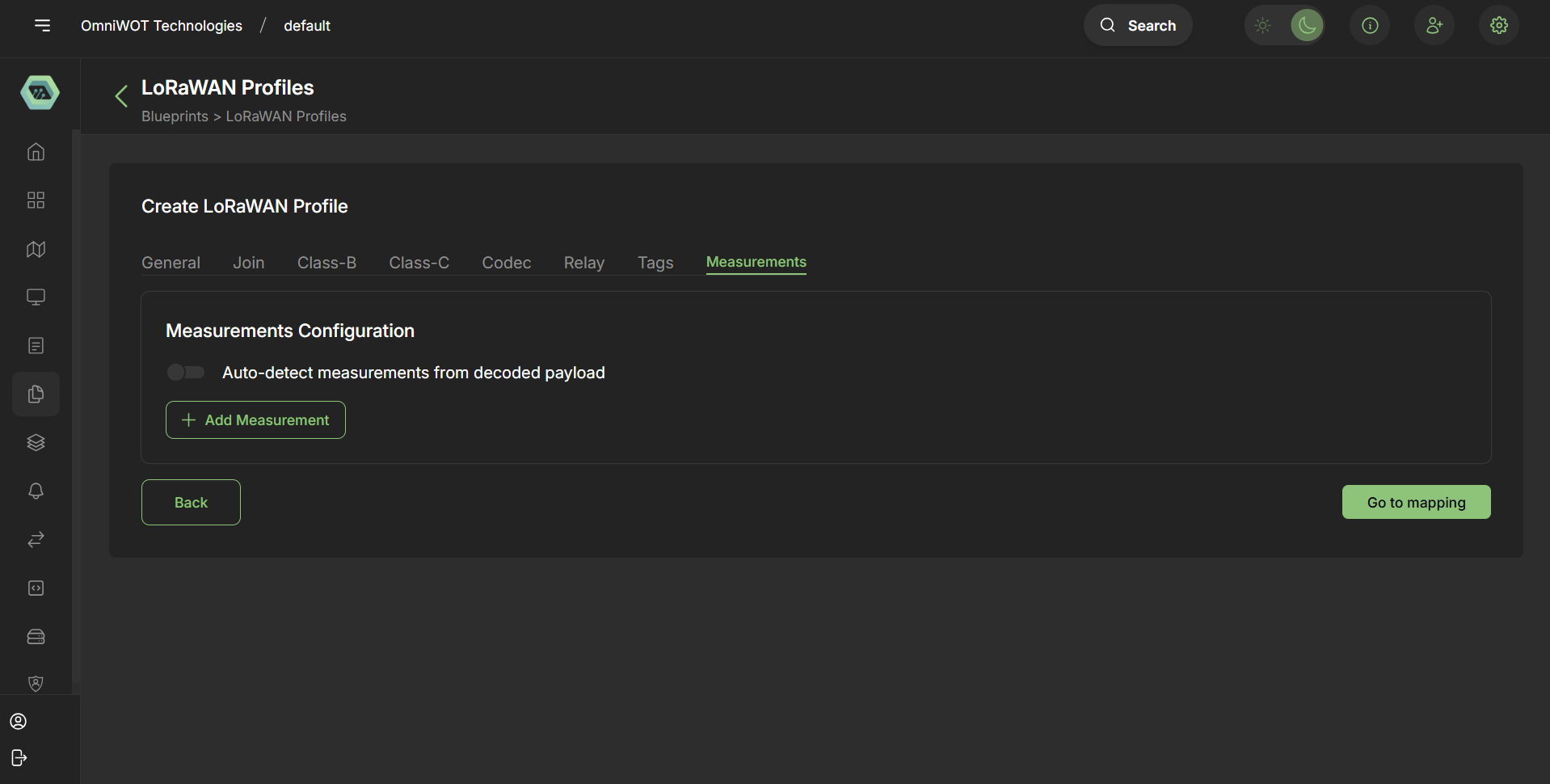
8. Measurements
Auto-detection from Codec
Manually add measurement keys
Supported Aggregation Views:
- Per hour (last 24 hrs)
- Per day (last 31 days)
- Per month (last year)
Steps to Create a LoRaWAN Profile in OmniWOT
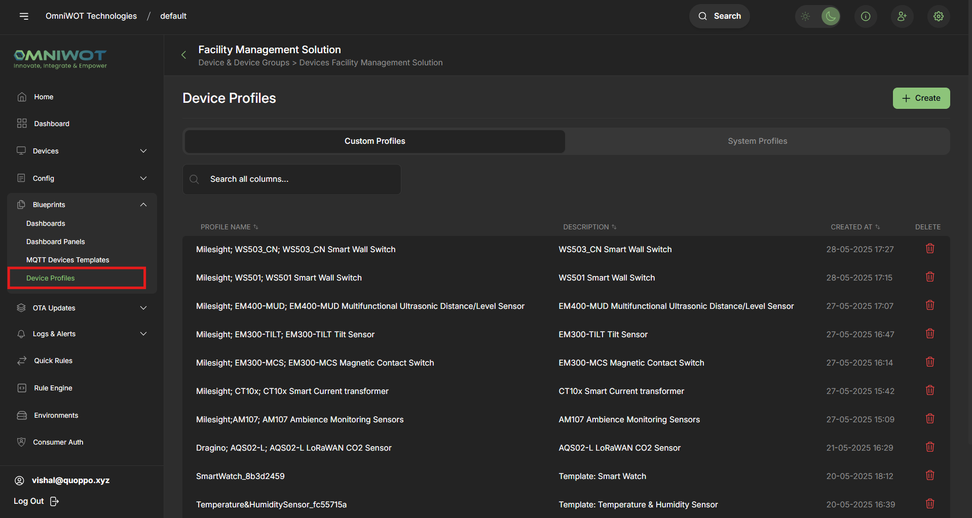
Step 1:
- Navigate to
Blueprints → Device Profiles
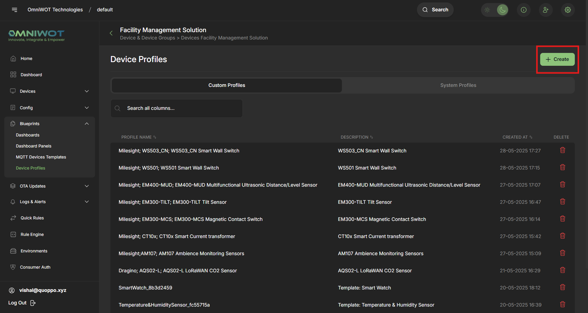
Step 2:
- Click on
Createto open the multi-step profile form
Step 3:
Complete the following sections step-by-step:
| Step | Section | Purpose |
|---|---|---|
| 1 | General | Basic identity and regional parameters |
| 2 | Join | OTAA/ABP activation settings |
| 3 | Class-B | Scheduled slot configuration for Class-B support |
| 4 | Class-C | Continuous downlink support for Class-C |
| 5 | Codec | Payload conversion configuration |
| 6 | Relay | Relay mode settings for repeaters or relay-capable devices |
| 7 | Tags | Add metadata and custom labels |
| 8 | Measurements | Configure measurements and visualization parameters |
General -
Join -
Final Step:
- Click
Skip Mapping and Createto finish profile setup or proceed to payload mapping.
Device Profile Mapping
Steps to map a device profile
Step 1
- Navigate to
Measurements → Go to mapping
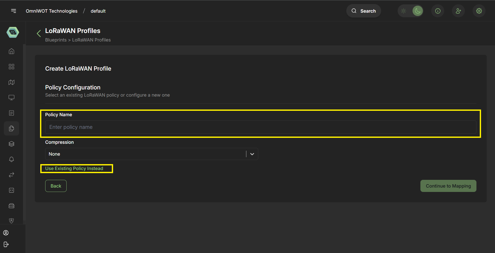
Step 2
- Enter Policy name and you can also select existing policy from the click use existing policy.
- Click on
continue to mapping
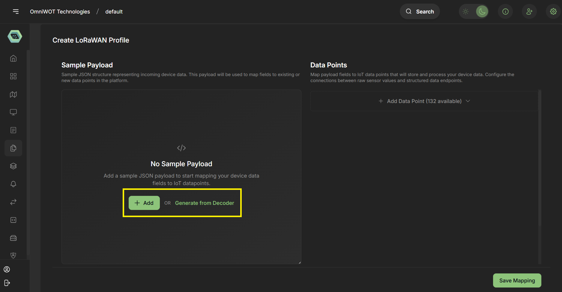
Step 3
- You have two options directly add json or you can also use genrate from LoRaWAN payload decoder (if you have a decoder function).
- For now creating through decoder function.
- Click on
Generate from decoder
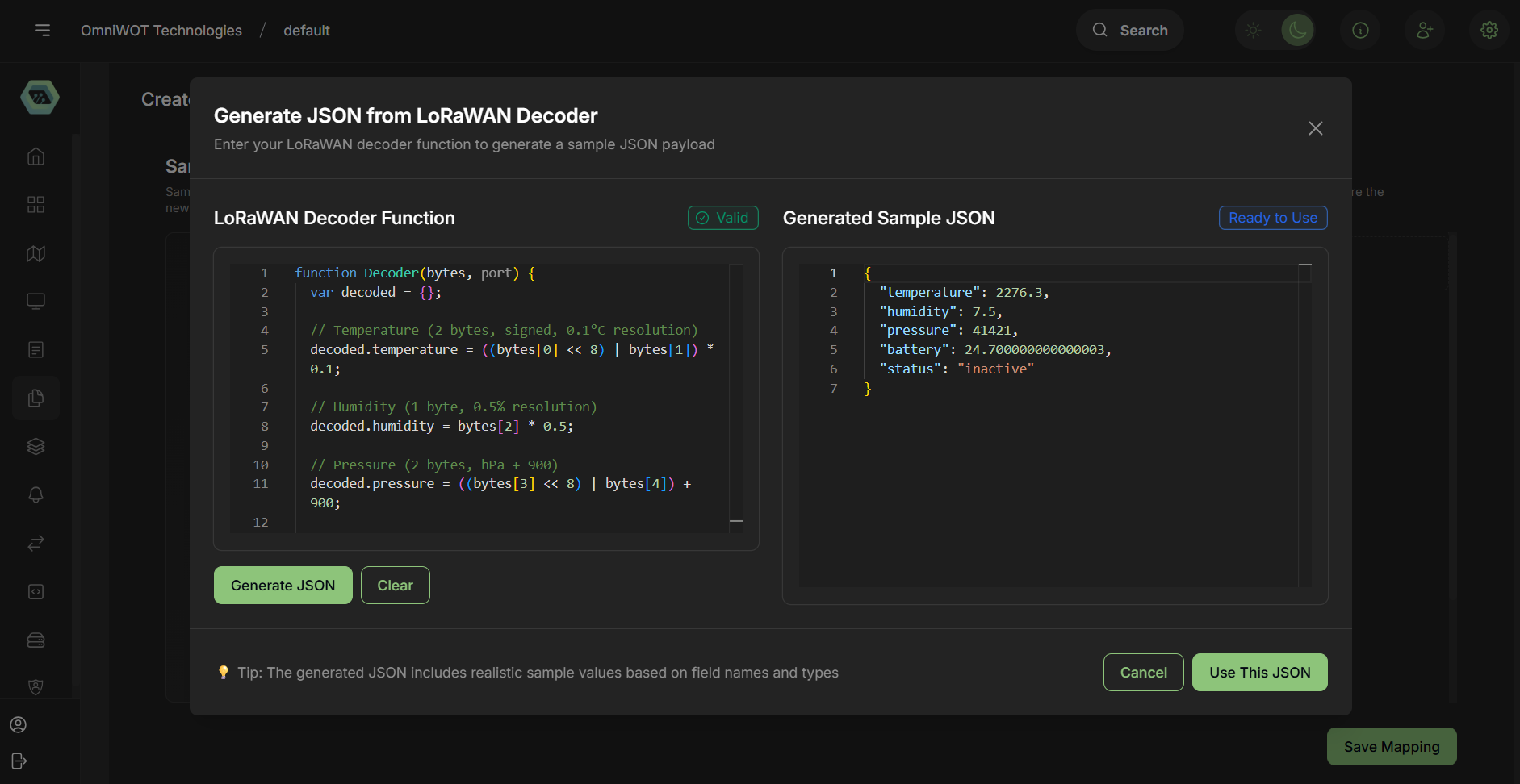
Step 4
- Enter the decoder function and click on
Generate JSON
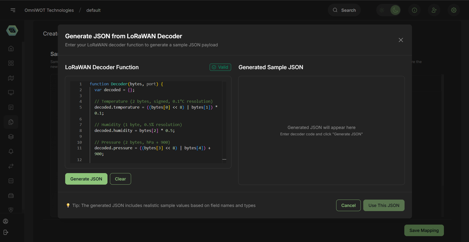
Step 5
- You can see the json in the preview section.
- Click on
Use This JSON
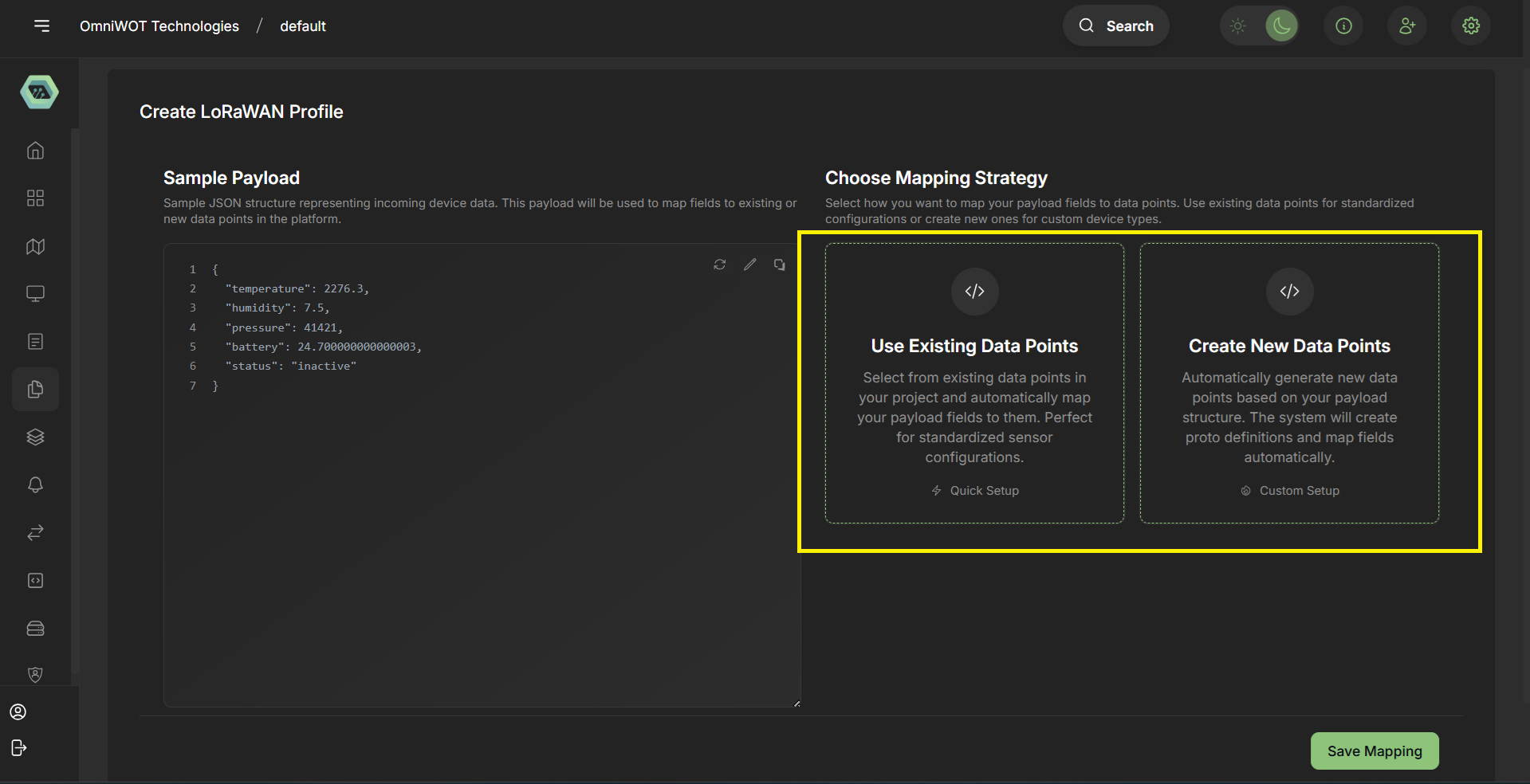
Step 6
- You can see the json in sample payload section, you can also edit the json.
- Now you have to select data point you can create new data point or you can select existing data point.
- Now i am clicking on
create new data point
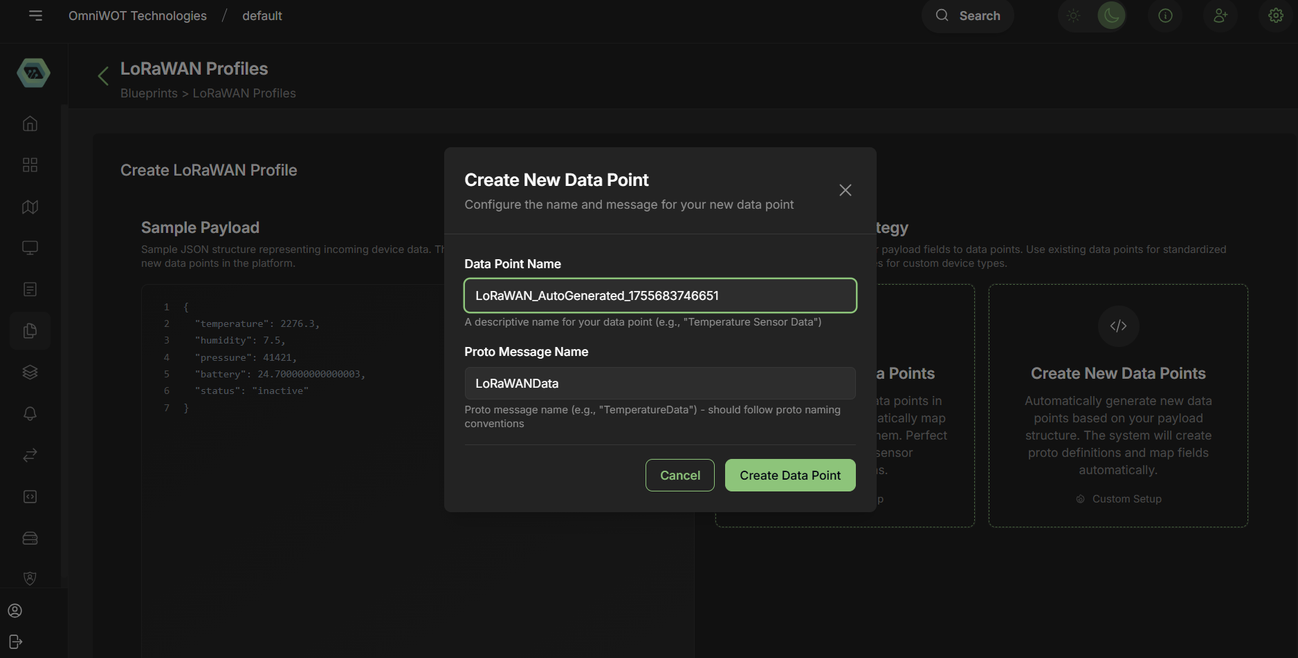
Step 7
- Opening create new data point form modal.
- Enter the data point name and proto message name
- Click on
create data point
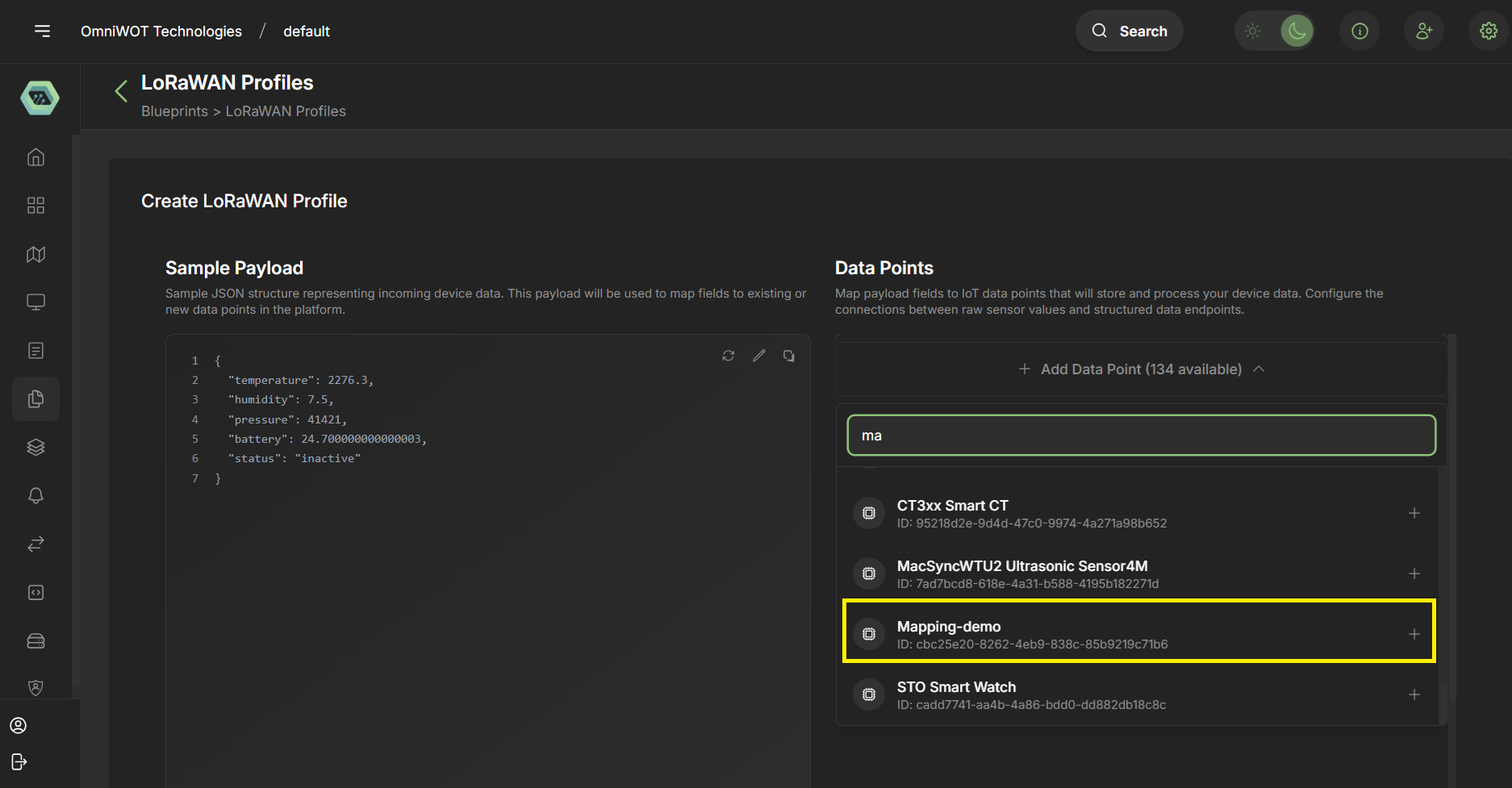
Step 8
- Now select the data point from the dropdown.
- Click on
+to add the data point.
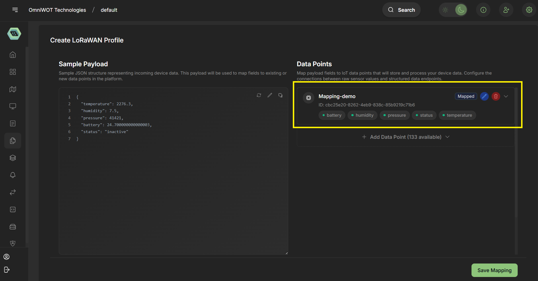
Step 9
- Now showing the selected data point also that is auto mapped.
- You can also add and remove multiple data point from here.
- You can also do manual mapping clicking edit icon.
Step 10
- Edit manual mapping by clicking edit icon.
- After Manual mapping click on
save mappingbutton.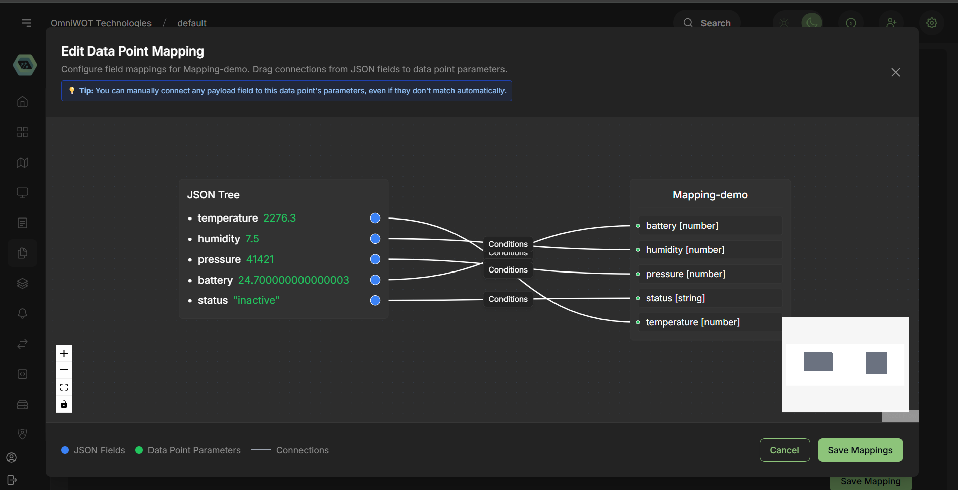
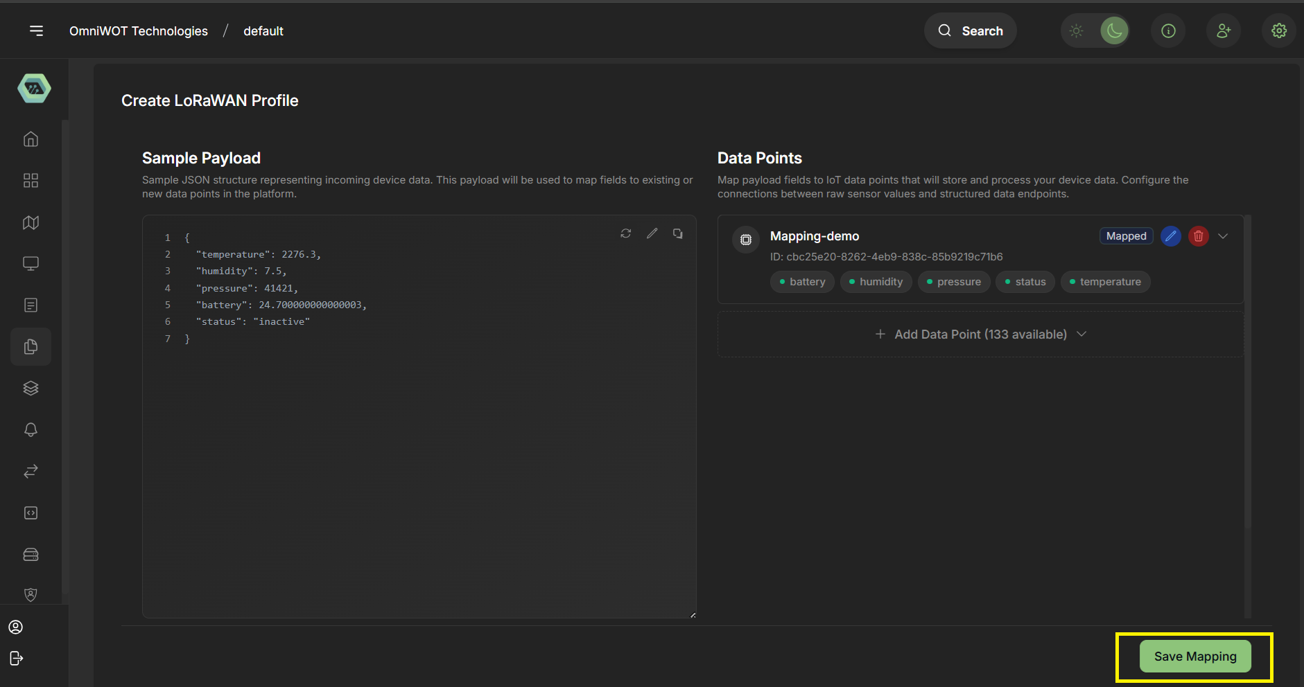
Step 11
- Click on
save mappingbutton
## **Key Differences: Custom vs. System Profiles**
| Feature | Custom Profiles | System Profiles |
|---|---|---|
| Editable | Yes | No |
| Purpose | User-specific or prototype devices | Standardized and vendor-certified |
| Codec Customization | Supported | Pre-defined |
| Tagging & Metadata | Fully customizable | Pre-filled from vendor |
| Measurement Configuration | Manual + Auto from codec | Auto based on default codec |
| Use Case | Experimental, niche deployments | Production-ready and validated setup |
Best Practices
- Prefer System Profiles when available for reliability.
- Use Custom Profiles for unique device use-cases or when System Profiles are insufficient.
- Always use OTAA activation unless ABP is mandatory.
- Configure measurement mappings to ensure accurate dashboard visualizations.
- Document all tag metadata for better organization and filtering.